1. In general, what causes magnetism?
2. What is electromagnetism?
3. What is the peculiarity involving magnetic north?
4. How could you find true (geographic) north?
5. What is a motor and how does it basically work?
6. What is electromagnetic induction?
7. What is a generator?
8. How do compasses respond to magnetic fields?
Monday, May 15, 2017
Saturday, May 13, 2017
Topics for final exam
The sheet of notes is still permitted.
The topics for the final exam are:
Diffraction and holography
electrical charge
proton, neutron, electron, quark - particles; which are fundamental and which are composite
atomic number and elements
Coulomb's law
charging things - what happens
voltage
current
resistance
units of V, I and R
series circuit
parallel circuit
basics of circuits
bulb brightness predictions - it's related to current
V = I R
basic electrical schematics (and symbols - battery, resistor, wire)
magnetism
electromagnetism
electromagnetic induction
motors
compasses
finding north
magnetic north vs. geographic north
generators (vs. motors)
You should definitely review demonstrations involving charge, light bulb brightness and removal, compasses, motors, etc.
Monday, May 8, 2017
Magnetism
Magnetism!
Similar to the case of charge, magnetic poles are divided into North and South poles.A North magnetic pole is one that points toward the Earth's magnetic north pole. This means that the Earth's magnetic north is ACTUALLY A SOUTH POLE (magnetically speaking).
Also:
- Like poles repel
- Opposite poles attract
- Each magnet must have at least one North and one South pole (though they may have more than one of each). There is NO such thing as a magnetic monopole.
- Magnetic fields are real, but the lines are imaginary - Field lines indicate the direction that a compass needle would take in the vicinity of the magnetic field.
- There are naturally occurring magnetic minerals - a very common one is called magnetite (Fe3 O4)
Magnetic north on the Earth is near Ellesmere Island in Northern Canada, several hundred miles from true (geographic) North (the North Pole). It is moving toward Russia at several miles per year.
For gory detail:
http://en.wikipedia.org/wiki/North_Magnetic_Pole
To find True/Geographic north, it is easiest to find Polaris (the current north star). Polaris is actually not all that bright, though in the top 50 brightest stars in the night sky. You need to find the Big Dipper (asterism at the rear end of Ursa Major). Follow the “pointer stars” at the end of the dipper. These visually lead you to Polaris. [If you were to follow the “arc” of the handle, you’d come to a bright star, Arcturus – “Follow the arc to Arcturus.”]

FYI:
https://www.youtube.com/watch?v=Ws6AAhTw7RA
The quantum levitation video shown in class.
https://www.youtube.com/watch?v=Ws6AAhTw7RA
The quantum levitation video shown in class.
How do we get magnetism?
Magnetic fields are related to electrons spins. Electrons act like tiny magnetic spinning tops. There is a tiny magnetic element associated with each electron spin. If the spins align, more or less, the object is said to be somewhat magnetic. More spin alignments (domains) means more magnetism. Materials that do this easily are generally said to be ferromagnetic.
As it happens, metals do this best (free electrons). In the core of the Earth, molten metal convects (rises and falls), giving the Earth a good magnetic field – measurable from the surface and beyond. Several planets have magnetic fields.
In general, the motion of charges leads to magnetic fields. If you have charge traveling through a wire, electrons can be thought of as moving together – this causes a magnetic field, also known as electromagnetism. The magnetic field caused by a current passing through a wire is often small, but if you coil the wire upon itself, the magnetic fields “add up”. Several hundred turns of wire (with current running through it) can produced quite a strong electromagnet.
A coil with current running through it can naturally react to a permanent magnet – if this is engineered well, we have a motor. See illustrations and demos in class.
>
Some images related to the above:


Below: basic motors


Electromagnetic Induction
Current causes magnetism – something shown in the early 19th century by Hans Oersted. As it happens, the reverse is also true – magnetism can cause current, but there must be some relative CHANGE in the magnetic field or location of conductor. There must be relative change – either coil or magnet must move, relative to the other.
This phenomenon, wherein a change in magnetic field relative to a conductor, generates electric current is called “electromagnetic induction.” It is the secret to understanding generators. If something, say moving water from Niagara Falls, can cause a coil of wire (in a turbine) to spin, current is generated. More spins of wire means more current.
It’s all about moving conductors in magnetic fields
In conclusion:
Electromagnetism:
Current (moving charges) cause a Magnetic Field
Electromagnetic Induction:
Change in magnetic field (through conductor), or vice versa (conductor moving through a magnetic field) causes an electric current. It's about RELATIVE MOTION between conductor (metal) and magnetic field.
Wednesday, May 3, 2017
Circuit questions
1. Describe the difference between voltage, current, and resistance. Give the proper units, too.
2. What is the resistance of a light bulb that allows 2 A of current through it when connected to a 12-V battery? (6 ohms)
3. A 5-ohm resistor is connected to a 10-volt battery. What current goes through the resistor? (2 amps)
4. In general, what is the difference between resistors in series and in parallel? Recall the light bulb examples and how the brightnesses compare.
3. A 5-ohm resistor is connected to a 10-volt battery. What current goes through the resistor? (2 amps)
4. In general, what is the difference between resistors in series and in parallel? Recall the light bulb examples and how the brightnesses compare.
5. Which has more resistance, 2 identical bulbs in series or the same 2 identical bulbs in parallel?
6. For question 5, which set-up (series or parallel) would "kill" the battery quicker?
7. You have 2 bulbs in series - remove one (unscrew it) and what happens?
7. You have 2 bulbs in series - remove one (unscrew it) and what happens?
8. You have 2 bulbs in parallel - remove one (unscrew) and what happens?
9. Draw the symbols for battery, resistance and wire. Draw a schematic for 2 resistors in series. Draw a schematic for 2 resistors in parallel.
10. Recall the basics of what it takes to make a light bulb light. Also recall the various light bulb brightness demonstrations from the past 2 classes.
10. Recall the basics of what it takes to make a light bulb light. Also recall the various light bulb brightness demonstrations from the past 2 classes.
Circuits II
OK, so about regular circuits:
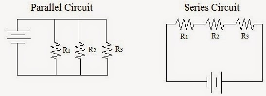
The images represent SERIES CIRCUITS and PARALLEL CIRCUITS.


In a series circuit, the current is constant and is set by the total resistance of the circuit (the sum of the resistors). If you remove one resistor (or light bulb, as in the first image), the current stops. If the resistors were identical bulbs, having more bulbs would result in dimmer bulbs, since the battery voltage is distributed among them. Note that the sum of the voltages "over" the bulbs is equal to the total voltage provided by the battery (give or take some minor losses). Identical bulbs (or resistors) have identical voltages "over" them - 3 identical bulbs connected to a 9-V battery would have roughly 3-V each over them.
In parallel circuits, current has multiple paths to take, so the total resistance of the circuit is actually LESS than if the resistors were alone or in series with other resistors - see details below. Since the bulbs are connected equally to the battery, they experience the same as the battery voltage - they are, therefore, of equal brightness (and the same brightness they would have if there were only ONE bulb connected). Of course, bulbs in parallel draw more current and thus cause a battery to die sooner. You could have 10 bulbs or resistors connected in parallel to a battery - each will be as bright as if only 1 were connected to the battery (same voltage over each), though 10 bulbs will kill the battery 10 times faster.
Does this have anything to do with holiday lights?
What I've written above is primarily geared toward identical bulbs. In series, add up the resistances to get the total resistance. In parallel, it is more complicated. There is a formula one can use (1/Rp = 1/R1 + 1/R2 + ...), but we will only concern ourselves with the case of identical resistors in parallel. In that case, divide the value of the resistor by the number of resistors to get the total effective resistance. For example, two identical 50-ohm resistors in parallel is the same as one 25-ohm resistor. This seems strange, but it's a little like toll booths - when one toll booth is open, it can get crowded (the current is small). With multiple toll booths open, the resistance is effectively less, so the current can be greater.
In the first image below, the graphic represents the schematic view of a parallel circuits, with 2 resistors. Note that 2 possible paths are available for current to take - current runs through EACH path, though there will be more current where there is less resistance. The total current from the battery is equal to the sum of the currents through the 2 resistors. It follows V = I R, though the V over each R is the same. The I through each will therefore be V/R.
The second image illustrates the series circuit concept: identical resistors in series will effectively give MORE resistance (the sum of the resistances, actually) to the battery, so the current will be LESS (and exactly the same in each resistor or bulb). It also easily follows V = I R, with more R yielding less I (when V is constant). Think of V = I R this way: I = V/R. More R, less I.


The second image illustrates the series circuit concept: identical resistors in series will effectively give MORE resistance (the sum of the resistances, actually) to the battery, so the current will be LESS (and exactly the same in each resistor or bulb). It also easily follows V = I R, with more R yielding less I (when V is constant). Think of V = I R this way: I = V/R. More R, less I.

Bulbs in Series - same current through each, but the voltage from the battery "splits"
Bulbs in Parallel - same voltage over each, but the current from the battery "splits"
Monday, May 1, 2017
Circuits 1
Thus far, we have only discussed "static" (stationary) charges. Static charges alone are useful, but not nearly as much as charges in motion. As you recall, electrons are the most easily moved particles. However, for sake of ease in sign convention (positive vs. negative), we define the following:

Resistance (R) - the ratio of voltage applied to an electrical device to the current that results through the device. Alternately: the amount by which the voltage is "dropped" per ampere of current.
So, what exactly IS a circuit?
What about power?
Current (I) - the rate at which positive charge "flows"
I = Q/t
The unit is the coulomb per second, defined as an ampere (A). Just as one coulomb is a huge amount of charge (nearly 6.3 billion billion protons), one ampere (or amp) is a tremendous amount of current - more than enough to kill a person. In fact, you can feel as little as 0.01 A. Typical currents in a circuit are on the order of mA (milliamperes).
Essentially, current is how quickly charge travels (or charge per time, q/t). The unit (a coulomb per second) is called the ampere (or amp, A). To keep things simple, we think about positive charge moving, even though it is really all about the electrons.
We need to define other new quantities in electricity: voltage, resistance, power.
Voltage (V) - the amount of available energy per coulomb of charge. The unit is the joule per coulomb, called a volt (V, in honor of Allesandro Volta, inventer of the battery).
V = E/Q
Batteries and other sources (such as wall sockets) "provide" voltage, which is really a difference between TWO points (marked + and - on a battery).
Resistance (R) - the ratio of voltage applied to an electrical device to the current that results through the device. Alternately: the amount by which the voltage is "dropped" per ampere of current.
R = V/I
You can also think of resistance as that which "resists" current. Typically, resistors are made of things that are semi-conductive (they conduct current, but less well than conductors and better than insulators). Resistors are often made of carbon, but can also be made of silicon and other materials. The unit is the volt per ampere, defined as an ohm (Greek symbol omega)
A convenient way to relate all of the variables is embodied in an expression often called Ohm's Law:
V = I R
So, what exactly IS a circuit?
An electrical circuit can be thought of as a complete "loop" through which charge can travel. Therefore, it actually has to be physically complete - there can be no openings. That is, the current actually has to have a complete path to take. I will demonstrate this in class with bulbs and wires; for now, see the image above.
https://phet.colorado.edu/en/simulation/circuit-construction-kit-dc
What about power?
Also consider electrical power (P). Power is the rate at which energy is used or expended: energy per time. Symbolically: P = E / t. The unit is the joule per second, called a watt (W). In electricity, power is also given by:
P = I V
P = I^2 R
Power allows us to express the brightness of a bulb. Consider that a 100-W bulb is brighter than a 60-W bulb.
Some folks like analogies. Consider a water analogy. Voltage is like a tank of water (how much water). Resistance is provided by a drain or faucet. The rate at which water comes out is the current. It's only an analogy, but it gets the gist of circuit terminology ok.
Subscribe to:
Posts (Atom)