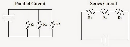
OK, so about regular circuits:
In a series circuit, the current is constant and is set by the total resistance of the circuit (the sum of the resistors). If you remove one resistor (or light bulb, as in the first image), the current stops. If the resistors were identical bulbs, having more bulbs would result in dimmer bulbs, since the battery voltage is distributed among them. Note that the sum of the voltages "over" the bulbs is equal to the total voltage provided by the battery (give or take some minor losses). Identical bulbs (or resistors) have identical voltages "over" them - 3 identical bulbs connected to a 9-V battery would have roughly 3-V each over them.
In parallel circuits, current has multiple paths to take, so the total resistance of the circuit is actually LESS than if the resistors were alone or in series with other resistors - see details below. Since the bulbs are connected equally to the battery, they experience the same as the battery voltage - they are, therefore, of equal brightness (and the same brightness they would have if there were only ONE bulb connected). Of course, bulbs in parallel draw more current and thus cause a battery to die sooner. You could have 10 bulbs or resistors connected in parallel to a battery - each will be as bright as if only 1 were connected to the battery (same voltage over each), though 10 bulbs will kill the battery 10 times faster.
Does this have anything to do with holiday lights?
What I've written above is primarily geared toward identical bulbs. In series, add up the resistances to get the total resistance. In parallel, it is more complicated. There is a formula one can use (1/Rp = 1/R1 + 1/R2 + ...), but we will only concern ourselves with the case of identical resistors in parallel. In that case, divide the value of the resistor by the number of resistors to get the total effective resistance. For example, two identical 50-ohm resistors in parallel is the same as one 25-ohm resistor. This seems strange, but it's a little like toll booths - when one toll booth is open, it can get crowded (the current is small). With multiple toll booths open, the resistance is effectively less, so the current can be greater.
In the first image below, the graphic represents the schematic view of a parallel circuits, with 2 resistors. Note that 2 possible paths are available for current to take - current runs through EACH path, though there will be more current where there is less resistance. The total current from the battery is equal to the sum of the currents through the 2 resistors. It follows V = I R, though the V over each R is the same. The I through each will therefore be V/R.
The second image illustrates the series circuit concept: identical resistors in series will effectively give MORE resistance (the sum of the resistances, actually) to the battery, so the current will be LESS (and exactly the same in each resistor or bulb). It also easily follows V = I R, with more R yielding less I (when V is constant). Think of V = I R this way: I = V/R. More R, less I.

The second image illustrates the series circuit concept: identical resistors in series will effectively give MORE resistance (the sum of the resistances, actually) to the battery, so the current will be LESS (and exactly the same in each resistor or bulb). It also easily follows V = I R, with more R yielding less I (when V is constant). Think of V = I R this way: I = V/R. More R, less I.

Bulbs in Series - same current through each, but the voltage from the battery "splits"
Bulbs in Parallel - same voltage over each, but the current from the battery "splits"


No comments:
Post a Comment